Web hello, in this video, i will show you a single phase motor wiring diagram with a capacitor start capacitor run capacitor connection. Unlocking the potential of your circuitwhen it comes to electrical projects, the wiring diagram is your map. Web steps for installing an ac dual capacitor wiring diagram.
Capacitor Start Motor Wiring Diagram Cadician's Blog
The first type is known as a start capacitor, which is responsible for providing the initial power to the system.
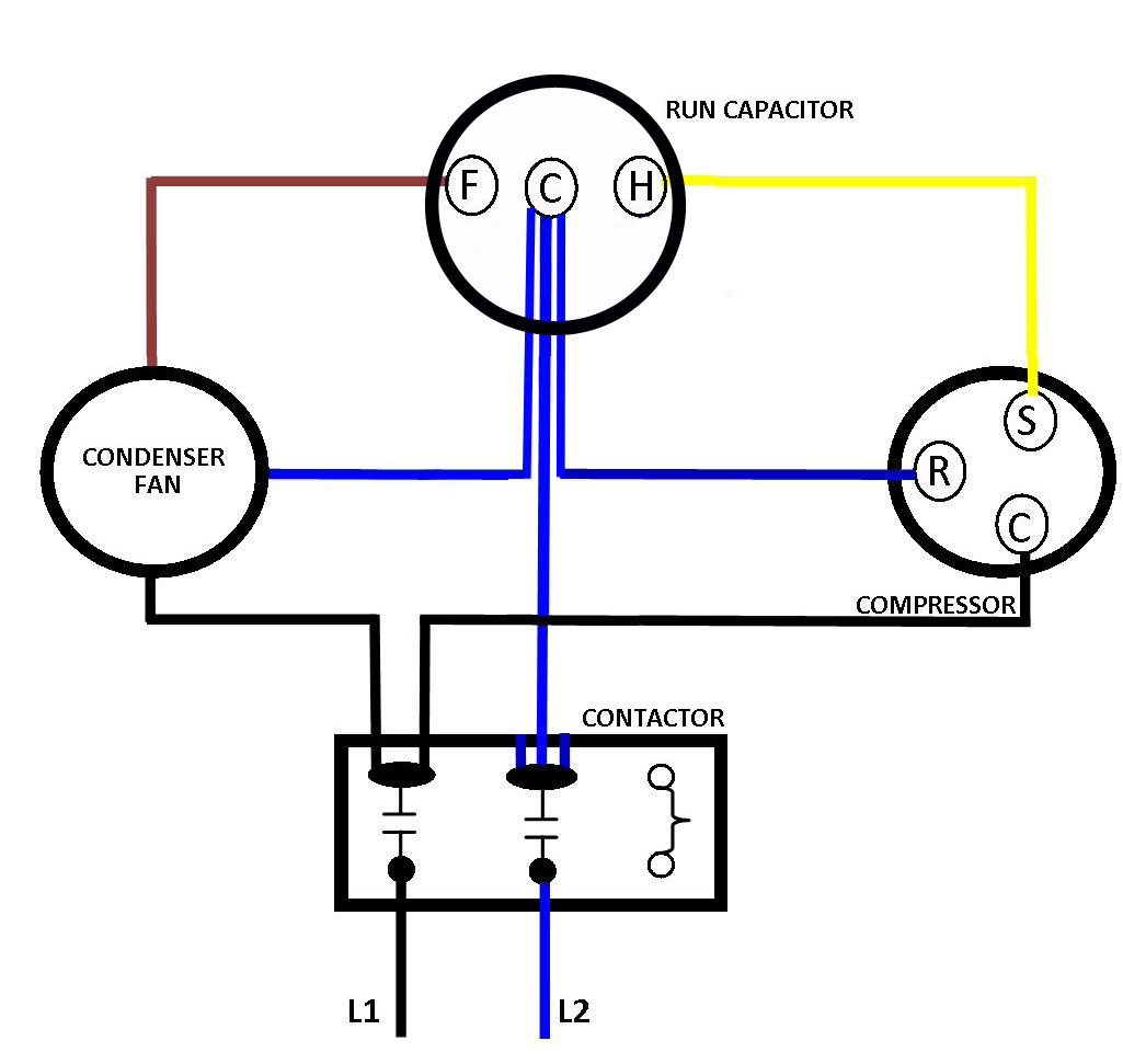
The Third Leg On A Dual Capacitor Is A Shared Common Leg (Labeled “C”).
How do capacitors work in an hvac system? The wiring diagram typically includes a legend that identifies the color of the wires and the corresponding connections. This document will help you wire the external capacitors to the pump.
Web Example Dual Round Hvac Capacitor Wiring Diagram A Dual Capacitor Will Have One Leg To Start The Compressor (Labeled Herm) And Another Leg To Start The Condensing Fan Motor (Labeled Fan).
Turn off the power supply to the air conditioner. How to go from a dual capacitor single in an air conditioner hvac. Web based solely on the information you presented, yes, this capacitor is probably suitable.
Web A Comprehensive Guide To Wiring Diagram For Dual Run Capacitor Components Of A Dual Run Capacitor.
You need it to know where everything goes and how to power it up. Web how to wire a dual run capacitor. Check the specifications of the manufacturer’s wiring diagram for dual run capacitors and make sure you have the.
S = Start Wire Connector
Web most wiring diagrams are fairly straightforward, outlining the connections needed to make the dual run capacitor operational. It also helps ensure that the capacitors are wired correctly in order to provide maximum performance. The second diagram is a schematic representation of the actual electrical connections.
It Will Also Show The Wires That Connect The Capacitors To The Air Conditioning Unit.
When troubleshooting an ac dual capacitor wiring diagram, it is important to understand that there are two types of capacitors used. Web wiring diagram for dual run capacitor: Web in our capacitor testing and wiring sketch above and in our explanatory table below, you note we use the letters s, c, and r to identify the usual terminals to which a start/run capacitor is wired.
The Herm Terminal Should Connect To The Yellow Wire Labeled S On The.
Connect the motor to the capacitor. Wiring diagram for dual run capacitor. Web using an ac dual capacitor wiring diagram.
Ac Capacitor Wiring Diagram And Connection Procedure Etechnog.
If so, how do i wire it up. Web a wiring diagram for dual run capacitor allows you to quickly troubleshoot any problems that may arise due to an incorrect or faulty connection between the two capacitors. Web generally, the wiring diagram for a dual run capacitor will involve connecting the two capacitors in series, so that both capacitors can provide the necessary power boost.
Wiring A Dual Run Capacitor Will Be Slightly Different For Every Ac Unit, But There Are Some General Guidelines That You Can Follow In Case You Don’t Know Where Each Wire Goes:
Capacitor motor an overview sciencedirect topics Connect the red wire to the ‘common’ terminal of the dual run capacitor and the black wire to the ‘fan’ terminal of your. It looks to me like black on rc1 as well as black and orange on rc2 goes to common on the dual and yellow on rc1 goes to herm on the dual and brown on rc2 goes to fan on the dual?
The First Diagram Is A Pictorial Representation Of The Electrical Connections And How They Are Connected To The Motor.
The steps for installing the wiring diagram are as follows: The second type is known as the run. Web follow these steps to wire your dual run capacitor:
On Many Systems These Terminals May Already Be Labeled So That The Three Leads On A Start/Run Capacitor Can Be Wired Correctly:
A dual run capacitor consists of two capacitors, a connection wire, and a fuse. Hvac shop talk podcast represents the blue collar boys and girls in the skilled. Web technical pages dual capacitor wiring diagram all homa single phase tp, a and grp series pumps utilize externally wired capacitors.
Web A Wiring Diagram For A Dual Run Capacitor Will Show The Two Separate Capacitors, Each With Its Own Electrical Connection.
Web the wiring diagram for a dual run capacitor consists of two separate diagrams. But what happens when you need to wire something that requires a dual run capacitor? Installing an ac dual capacitor wiring diagram is relatively simple, but it is important to ensure that it is done correctly.
Locate The Dual Run Capacitor.
Additionally, the wiring diagram will include a switch, also connected in series, that allows you to switch between the two capacitors when you need to. Web in this video, zack psioda explains how many dual run capacitors are wired in heat pump and air conditioner systems. It is usually located near the compressor or the fan motor.
Web Can I Replace The 35 Uf Capacitor And The 6 Uf Capacitor With A 35/5 Uf Dual Capacitor?
It also provides warnings about not crossing the positive and negative terminals. Web electric motor capacitor test procedures. When wiring a dual run capacitor, it is important to follow the.
Your Pump May Be Provided With A Start Capacitor And One Or Two Run Capacitors Along With A Potential Relay.
And your wiring is correct: Web here are the steps to wire a dual run capacitor: